
Order Related
Shipping, returns, warranty, and what is in the box
We try to fulfill all in-stock items the same day. Techna-Fit items may take up to 3 business days to ship.
KFE delivery estimates within the continental United States:
- Free shipping ships via USPS Ground Advantage — allow 2–7 days.
- USPS Priority Mail — allow 1–5 business days.
These are our own estimates and we deliberately allow extra time. USPS publishes its own service standards (currently 2–5 days for Ground Advantage and 2–3 days for Priority Mail); actual delivery is determined by USPS, not by KFE, and can run longer during peak periods or severe weather.
We can ship to any address in the United States and its territories. We do not ship to international destinations.
Full details: Shipping & Returns.
- Most new, unopened items: 30 days from delivery for a full refund. This includes brake pads, hardware, Techna-Fit brake lines, and all Stahlbus products.
- Clearance items cannot be returned.
- Techna-Fit clutch lines, and Techna-Fit brake lines used for a brake caliper swap or other custom application—including longer lengths, front-set-only, or rear-set-only orders—are final sale. Where an option is marked "No Returns" on the product page, all sales are final on that option.
- If the return is our error (wrong or defective item), we pay the return shipping.
- Refunds can take up to four weeks total: 5–10 business days transit, 3–5 business days for us to process, and 5–10 business days for your bank.
Full policy: Shipping & Returns.
Your tracking number is added to your order status, and an email is sent to the address on file.
You can follow live shipment tracking at USPS.com.
Orders can be cancelled any time before the item ships. Because we try to fulfill in-stock items the same day, cancellation cannot be guaranteed.
If you decide to cancel, please contact us immediately at [email protected] or (562) 941-8808. The sooner you reach us, the better the chance we can stop the order before it leaves.
Yes — and it helps to know who warrants what.
KFE Brake Systems warrants KFE brake pads:
- KFE QuietAdvanced Ceramic Brake Pads: 2 years or 25,000 miles, whichever comes first.
- KFE Quiet Comfort OE Semi-Metallic Brake Pads: 1 year or 15,000 miles, whichever comes first.
Techna-Fit and Stahlbus warrant their own products. Techna-Fit offers a Limited Lifetime Warranty on Techna-Fit parts, and Stahlbus offers a Limited Lifetime Warranty on Stahlbus parts. Those warranties are provided by those manufacturers, not by KFE. Contact Techna-Fit or Stahlbus directly for their full terms.
The KFE brake pad warranty runs from the date of delivery. Brake pads and brake disc rotors must be installed by an ASE-certified mechanic (ASE A5 Brakes certification recommended). To make a claim, request an RMA number from us at [email protected] or (562) 941-8808, and present an invoice showing the repair facility name, the mechanic's ASE certification number, the date of installation, and the vehicle mileage.
The KFE warranty does not cover product modification or alteration, or damage caused by misuse, abuse, other faulty parts, improper installation, track racing, negligence, lack of maintenance, off-road use, or abnormal operation. Coverage ends when you sell the vehicle. Return shipping to and from our warehouse is the customer's responsibility.
Some States do not allow the exclusion or limitation of incidental or consequential damages, so the above limitation or exclusion may not apply to you. This warranty gives you specific legal rights, and you may also have other rights which vary from State to State.
Full terms: Limited Warranty.
- Log into your account by clicking on My Account (top right corner) > Sign in
- Once signed in, it should take you to Orders automatically.
- Find the order you would like to return.
- Select the return items option shown for that order to start a return.
- For more questions, or if you do not see a return option on your order, please email us at [email protected] or call (562) 941-8808 and we will send you return instructions.
Before you start: most new, unopened items can be returned within 30 days of delivery, including Techna-Fit brake lines and Stahlbus products. Clearance items cannot be returned. Techna-Fit clutch lines, and Techna-Fit brake lines bought for a caliper swap or other custom application (longer lengths, front-set-only, rear-set-only), are final sale — these are marked "No Returns" on the product page. See Shipping & Returns for the full policy.
- One order of either front or rear brake pads includes four individual pads—two for each caliper.
- Each pad comes with a pre-attached shim.
- Brake warning sensor (when applicable).
- Most brake pad sets do not include additional hardware.
Shop KFE brake pads.
- Typically, a set includes 3, 4, 5, 6, or 8 stainless steel braided hoses, depending on the application. Most vehicles generally require 4 brake hoses—two front and two rear.
- If a hose features a banjo end fitting, it will include one banjo bolt and two copper washers per hose.
- Some kits may also include brackets, U clips, or C clips, depending on the application.
- One oil drain plug of the selected size
- One connector for draining oil
- One hose to connect to the connector
- One dust cap
- If ordering a retainer cap kit, both the standard and retainer caps will be included
Shop Stahlbus oil drain plugs.
Generally one bleeder valve with one dust cap per order. If you order more than one, you receive one dust cap per bleeder valve.
Shop Stahlbus bleeder valves.
Product Related
Choosing the right pads, rotors, and brake lines
Use Shop By Vehicle to check fitment for KFE Brake Systems brake pads and Techna-Fit stainless steel braided brake lines.
For all other products, please reach out and we will confirm and verify fitment for you: [email protected] or (562) 941-8808.
A few things that affect fitment and are worth double-checking before you order: brake pads can vary by trim level, engine, first letter of the VIN, fuel type, standard vs heavy duty brakes, and drivetrain configuration (FWD/AWD). Front and rear pads are almost never interchangeable. Brake lines are vehicle-specific and are almost never interchangeable.
While some brake pads are interchangeable between different vehicles, most are vehicle-specific and some may vary based on trim level, engine, first letter of the VIN, fuel type, standard vs heavy duty brakes, and drivetrain configuration (FWD/AWD). Please double-check fitment for your specific vehicle before purchasing to ensure proper compatibility.
Front and rear brake pads are almost never interchangeable, except in very rare cases. For the vast majority of vehicles, front and rear pads differ in shape, size, and design, making them non-interchangeable. Always verify the correct application for each axle before purchasing.
Here are a few things you should consider to determine what type of brake pads to purchase.
- Price
- Noise level
- Dust Level
- Durability
- Rotor Life
- Consistency of Coefficient of Friction
- High temperature resistance (without brake failure)
Shop KFE QuietAdvanced Ceramic Brake Pads. All KFE friction material is 100% asbestos-free.
Brake lines are vehicle-specific and are almost never interchangeable. Please refer to the vehicle compatibility chart to ensure proper fitment.
Important Notice for Brake System Swaps:
If you are performing a brake swap—installing calipers from Vehicle A onto Vehicle B (of a different make, model, or trim)—please note that all sales are final and returns will not be accepted for these custom applications.
Brake hoses must be matched to the exact application. Confirm every one of the following before ordering:
- Fitting type at each end (banjo, inverted flare, and so on)
- Thread size and pitch
- Seat / sealing surface type
- Overall length
- Routing and bracket locations, checked through full suspension travel and full steering lock in both directions
If you are fitting a caliper from a different vehicle, the caliper-side fitting will commonly follow the caliper's original application, and the chassis-side fitting will commonly follow the vehicle the hose mounts to. Treat that only as a starting point for narrowing your search—never as a substitute for verifying every dimension listed above against the actual parts in your hands.
Brake hoses for on-road use in the United States are regulated under FMVSS 106 (49 CFR 571.106), whose stated purpose is "to reduce deaths and injuries occurring as a result of brake system failure from pressure or vacuum loss due to hose or hose assembly rupture." A hose that is too short can be pulled tight at full droop or full lock. A hose that is too long can contact a tire, wheel, or suspension component and chafe through. Both fail the same way.
Brake Hose Length Disclaimer & Limitation of Liability
Extended brake hoses (e.g., +2" or +4") are offered strictly for custom applications. These products are not intended for use as standard or OEM replacements, and any modification to brake line length falls outside manufacturer specifications and recommendations.
Use of extended brake lines in non-custom or OEM-replacement setups may result in improper fitment, contact with suspension or brake components, and potentially lead to brake system failure, including—but not limited to—loss of braking performance, property damage, bodily injury, or death.
By purchasing or installing non-standard brake hose lengths, the end user expressly assumes all risks associated with their use. Furthermore, the user agrees to release, indemnify, and hold harmless Techna-Fit, KFE Brake Systems, and any affiliated parties from and against any and all claims, liabilities, damages, losses, or expenses—including legal fees—arising from the use, misuse, or installation of modified or extended brake hose products.
Warranty coverage applies only to products used in the original equipment (OE) application for which they were sold. Products installed outside OE specification—including custom brake swaps, modified or extended brake hose lengths, and any non-OE application—are not covered by any Techna-Fit or KFE Brake Systems warranty. To the maximum extent permitted by law, Techna-Fit and KFE Brake Systems disclaim all liability arising from use outside OE specification. All customers are strongly advised to consult a certified technician and strictly follow OEM specifications for all safety-critical components.
Brake pad life depends on many factors such as brake pad formula, rotor type, if a rotor is drilled or slotted, how hard you brake, how frequent you brake, among other things. Imagine a truck driver starting from New York City drives to Los Angeles. The driver might drive one to two thousand miles using their brakes minimally. Now imagine you live in Los Angeles, and you have to drive on the 405 Freeway for 15 miles every day to and from work. You may have to use your brakes for 30 minutes out of the 45 minutes you are traveling. To ensure the longevity of your brake pad's life, we recommend you follow safe driving practices promoted by the DMV.
Shop KFE brake pads.
Yes, they do something—but not always what people expect. Slotted rotors help clean off dirt and let gas escape between the braking contact areas, which improves the efficiency of your braking. Drilled rotors help vent gas and water from the pad surface and can improve initial bite in wet conditions.
CAUTION: Cross-drilling removes material and reduces pad contact area. Drilled rotors that are not engineered for the specific application can develop cracks under sustained high heat. Race teams invest heavily in research to understand how many holes there should be, where the holes should be drilled, the hole diameter, the chamfer angle, and what type of materials are used on the rotor, among other things, to decrease the chance that a drilled rotor will crack under extreme pressure and heat. Keep in mind that by gaining a cleaner contact surface and a cooler rotor, you are also losing contact surface between the brake pad and the brake disc.
Thermo Scorched refers to a manufacturing step that heat-treats the friction surface of the brake pad in a high-temperature oven after the pad is molded. All KFE brake pads go through this process.
The purpose is to burn off uncured resins and volatile agents left in the friction surface after manufacturing. Those are the agents that would otherwise have to cook off during the first hard stops on your car. The intent is to shorten the initial bedding-in period compared with an untreated pad.
Note that scorching is a separate operation from post-curing: post-curing stabilizes the material itself, while scorching heat-treats the surface that meets the rotor.
Shop KFE brake pads.
Positive Molding is a manufacturing process that uses heat and pressure to press the premixed brake formula (friction surface or brake pad) onto the back plate. Imagine Luke from Star Wars being trapped inside the trash compactor, and the two walls are closing in. Now the two walls will be heated, one side will have the back plate and the other side pushes down the premixed brake formula onto the back plate.
The key benefit of this process is consistent friction material density through the full thickness of the pad. Because the density is uniform rather than varying from the surface down to the backing plate, braking feel stays more consistent as the pad wears.
Shop KFE brake pads.
Yes, there are other ways to cool a rotor besides drilling. Most vented rotors have straight vanes between the inner and outer disc faces. The vanes let cool air in and hot air out, which helps carry heat away.
There are two other common designs:
- Curved vane rotors use directional curved passages, which can increase the mass of air moved through the rotor. Because they are directional, they are side-specific—a left and a right rotor are not interchangeable.
- Pillar vane rotors replace continuous vanes with an array of posts. These are a different concept, not simply curved vanes: the pillars increase turbulence and heat-exchange surface area, and can improve crack resistance.
Each design can improve airflow or heat transfer when it is engineered for the specific application. Some manufacturers also use slots on the rotor face to help move air and clear debris across the braking surface.
Technical Related
How brakes work, installation, and troubleshooting
WARNING: Brakes are a safety-critical system. Proper brake work requires training, the right tools, and a safe working area. If you are not confident performing every step below, have a qualified repair facility do the work. Always follow your vehicle manufacturer's service information—it provides the torque specifications, caliper piston procedure, and any special steps your vehicle requires. Where your vehicle's service information differs from this general overview, follow your vehicle's service information.
This is a general outline of what the job involves, not a substitute for your vehicle's procedure.
Before you lift the vehicle
- Park on level, solid ground. Set the parking brake and chock the wheels that stay on the ground.
- Wear eye protection and a correct-rated safety mask—brake dust and rust should not be inhaled.
- Break the lug nuts loose slightly while the wheel is still on the ground.
- Avoid using a scissor jack. A scissor jack is meant for a quick roadside tire change, not a long job, and it can be unstable. Make sure whatever jack and stands you use have a lift capacity that meets or exceeds your vehicle's weight.
- If your vehicle has an electronic parking brake, it usually must be put into service mode with a scan tool before the rear caliper pistons can be retracted. Check your service information first.
Removing the old pads
- Lift the vehicle and support it on properly rated jack stands. Never work under a vehicle held up only by a jack.
- Remove the wheel and inspect the brake hose, caliper, and rotor before touching anything.
- On a typical floating caliper, remove the 2 caliper guide pin bolts on the inner/back side of the caliper and lift the caliper away. Fixed and opposed-piston calipers, and some other designs, come apart differently—check your vehicle service information before removing anything.
- Support the caliper on a stand or hanger. Never let it hang by the brake hose—that can damage the hose internally where you cannot see it.
- Slide out the old pads and remove the pad hardware from the bracket.
Preparing the parts
- Clean the caliper bracket where the hardware seats. Install the new hardware that came with your pads—do not reuse flattened or rusted hardware.
- Retract the caliper piston slowly using the correct tool. Many rear calipers must be screwed in rather than pushed; forcing one straight in will damage it.
- Watch the brake fluid reservoir as you retract pistons. The level rises, and it can overflow.
- Clean rust off the hub face and the inside of the rotor before fitting the rotor. Debris here is a common cause of run-out and pedal pulsation.
- Make sure the brake pad friction material faces in toward each other—that is, toward the rotor on both sides. The steel backing plates face outward.
Installing and finishing
- Fit the rotor, then the new pads, then reinstall the caliper. Torque the caliper bolts to your vehicle manufacturer's specification with a torque wrench.
- If your pads came with anti-drag caliper springs, they can be difficult to fit with the caliper fully assembled. An easier sequence: hold the rotor in place with one lug nut, bolt the caliper mounting bracket to the vehicle, then load the bracket with the pads and the anti-drag springs together before fitting the caliper body. That way you get both jobs seated correctly at once—the pads into the hardware, and the springs onto the pads.
- Reinstall the wheel and torque the lug nuts to specification in a star pattern—not in a circle, and not with an impact gun alone.
- Lower the vehicle.
Before you drive: pump the brake pedal until it is firm. The pistons were retracted, so the first few pedal presses only take up that slack. Do not move the vehicle until the pedal feels normal. Then check the brake fluid level and check for leaks. Test the brakes at low speed in a safe area before driving normally.
Finally, follow the instructions supplied with your pads for bedding in. See How do I bed in new brake pads?
Shop KFE brake pads.
Always follow the instructions supplied with your specific pad set. Bed-in procedures differ by friction formulation. Some manufacturers publish their own procedure, and some state that no break-in is required at all. Where the manufacturer provides instructions, those instructions control—not this page.
Breaking in or bedding in does two things. The first is to burn off chemicals and resin left on the pad, and secondly to lay down a transfer layer or transfer film between the pad and rotor. As you may have already read, EACH and EVERY one of our brake pads goes through the Thermo Scorched process, which helps burn off chemicals and resin left behind on the brake pad after it is manufactured. We still want that transfer layer to go on the rotor. We recommend you break in or bed in your new brake pads, but your brakes will still work should you choose not to go through this process. Remember if you have old rotors, we highly recommend getting them resurfaced or installing new rotors, and also cleaning the surface of the rotor with warm soapy water both FRONT and BACK after the rotor has been resurfaced.
If no instructions came with your pads, here is a general procedure:
- Recommended to be performed on a closed or empty roadway to avoid endangering pedestrians and properties. Do not break any traffic safety laws while attempting the break-in session.
- Accelerate the vehicle to 35mph, and then firmly depress the brake pedal to 5mph. If anti-lock braking system (ABS) is activated, lift pressure to the brake pedal until ABS is deactivated. Do not at any time during this process completely depress and hold the brake pedal down during a stop – this will cook the brakes and may create hot spots on the new rotor.
- Repeat the step above 10 times. A burning smell during this process is common. If you see smoke, stop the procedure and allow the brakes to cool.
- Avoid coming to a complete stop with your foot resting on the brake pedal. Holding the pedal down on a hot rotor can imprint pad material onto the rotor surface, which causes vibration and pedal pulsation later.
- Drive several minutes while minimizing the use of your brakes to cool down your rotors to near ambient temperature.
If you notice brake fade during this process — the pedal still feels firm but the vehicle takes longer to stop — stop the procedure, pull over safely when it is safe to do so, and allow the brakes to cool before driving normally. If the brake pedal itself feels soft, spongy, or sinks toward the floor, stop driving and have the vehicle inspected by a professional immediately. That can indicate boiling brake fluid, air in the hydraulic system, or a hydraulic fault, and it will not simply cool off and go away.
For the correct rotor installation process, see Do I need new rotors when I replace brake pads?
Not always — but the old rotors must be inspected first, and they must pass. Before reusing a rotor, check it against your vehicle manufacturer's service criteria:
- Thickness. Measure with a micrometer. A rotor at or below the manufacturer's minimum thickness must be replaced. It cannot be machined back into service. A rotor below minimum has less material to absorb and shed heat, and less structural integrity.
- Lateral run-out and thickness variation (DTV). Measure with a dial indicator against the manufacturer's specification.
- Surface condition. Check for scoring, grooves, heat cracks, and hard spots. A rotor surface that is not smooth will lead to more brake noise and pedal pulsation.
KFE recommends new rotors, or machining rotors that are still safely above minimum thickness, whenever you replace brake pads. New or freshly machined rotors give the best contact between the pad and the rotor surface, which helps reduce brake noise, pedal pulsation, and comebacks.
Correct process when installing new brake pads:
When new rotors or turned/resurfaced old rotors above minimum thickness are used during a brake pad change, there will be better contact between the surface of brake pads and rotors. This will help reduce brake noise, pedal pulsation, and fewer comebacks.
Even when new rotors or turned rotors are installed, run-out can still happen early on. A few key things help reduce run-out when installing rotors.
- Remove all rust on the hub surface, and on the inside contact areas of the rotor (if old rotors are used) with a metal brush. This will help to have a full contact surface between the brake pad and rotor, and help reduce lateral run-out. Wear a correct-rated safety mask to prevent inhaling brake dust, rust, and debris during this process.
- Put on your rotor with lug nuts to hold it in place, then measure for lateral run-out. Specifications vary by vehicle. As an example, many modern vehicles specify 0.002 inches (0.05 mm) or less, while some manufacturers allow more on an existing rotor. Always use your vehicle manufacturer's published specification—it is the one that controls.
- Install the brake pads per the manufacturer's guidance.
Brake noise is the number one issue that all leading manufacturers and automakers are trying to resolve. There are three main categories of brake noise frequencies caused by different materials and driving conditions, and a multitude of causes of brake noise. In our experience, no brake pad is completely silent under every condition, so be cautious of any claim of a completely noise-free brake pad. What we try to do is find the best compromise between pad life, noise, and dust. We also use noise reducing shims. The shims reduce vibration and noise to make your driving experience more comfortable.
A high-pitched squeal that comes and goes with the brake pedal may be a wear indicator. Wear indicators are not universal: some pads use a mechanical tab that contacts the rotor and squeals once the friction material wears down, some use an electronic sensor that lights a dashboard warning instead, and some have neither. Check what your pads and your vehicle actually use. Where a mechanical tab is fitted, that squeal is a warning telling you to have the brakes inspected and the pads replaced.
Squealing can also be caused by debris caught between the pad and the rotor, or by the brake pad material itself. In those situations we recommend cleaning the brake contact surfaces and performing the break-in procedure again.
Grinding needs inspection, and it needs it now. A grinding noise during braking often means the friction material has worn away and the backing plate is contacting the rotor—but it can also be a stuck caliper, a failed wheel bearing, a heat-shield contacting the rotor, or debris trapped in the brake. Stop driving and have the brakes inspected before continuing. Do not assume it is only worn pads, and do not keep driving on it: whatever the cause, it is affecting your ability to stop.
WARNING: Replacing a brake hose opens the hydraulic brake system. The system must be correctly bled afterward, and the vehicle is not safe to drive until it is. This job requires training, the correct tools, and confidence in your own work. If you are not certain you can complete every step including a proper bleed, have a qualified repair facility do it. Always follow your vehicle manufacturer's service information for torque values and bleeding sequence.
This is a general outline of what the job involves, not a substitute for your vehicle's procedure.
Before you start
- Confirm your new hoses match the application—fitting type, thread, seat, and length—before removing anything.
- Have fresh, correct-specification brake fluid from a sealed container. Brake fluid absorbs moisture from the air. An already-opened bottle absorbs moisture, and moisture lowers the boiling point of the fluid. Under heavy braking the water can boil and form vapor bubbles. Brake fluid is essentially incompressible, but vapor is compressible—so the pedal goes soft and braking is lost. That is why sealed, fresh fluid matters.
- Brake fluid damages paint. Cover painted surfaces and keep rags and water nearby.
- Wear eye protection and gloves.
Removing the old hose
- Lift the vehicle and support it on properly rated jack stands. Remove the wheel.
- Use a flare nut wrench on the hard line fitting, not an open-end wrench. Open-end wrenches round these fittings off, and a rounded fitting turns a one-hour job into a much larger one.
- Loosen the hard line fitting first, then remove the retaining clip that holds the hose to the bracket.
- Some applications have a mid bracket holding the hose to the strut or to the chassis. Remove that bolt to free the hose.
- At the caliper end, remove the banjo bolt or the threaded fitting. Have a container ready—fluid will drain.
Installing the new hose
- Always use new copper washers on banjo fittings. One on each side of the banjo. Never reuse old crush washers; they are designed to deform once.
- Route the new hose exactly as the original was routed, through the same brackets and supports.
- Do not twist the hose. A braided line should be installed with no twist along its length.
- Techna-Fit recommends 12–14 ft-lbs on the banjo bolts, on the end fittings, and on the hard line fitting the end fitting threads into. Over-tightening a banjo bolt can crack it. Always confirm against the instruction sheet supplied with your kit.
Check clearance before you bleed
- With the wheel off, cycle the steering fully left and fully right, and move the suspension through its full travel.
- Confirm the hose never contacts the tire, wheel, suspension, or any sharp edge, and is never pulled tight at full droop.
- A hose that is too short will be stretched at full extension. A hose that is too long will rub through. Both fail the same way.
Bleed the brakes and verify before driving. Bleed in the sequence your vehicle manufacturer specifies, keeping the reservoir topped up so you do not draw air back into the system. Then, with the vehicle stationary, press the brake pedal firmly and hold it—the pedal must feel firm and must not sink toward the floor. Inspect every fitting for leaks under pressure. If the pedal is soft or sinking, or you find any leak, do not drive the vehicle.
Finishing up
- Reinstall the wheel and torque the lug nuts to specification in a star pattern.
- Lower the vehicle.
- Test the brakes at low speed in a safe area before driving normally, and re-check for leaks afterward.
WARNING: To perform automobile repairs requires professional training, tools, equipment, and a facility in automotive services. The following is meant for professionals. Please consult the nearest professional auto mechanic to help correct any warping issues. To the maximum extent permitted by law, we will not be held responsible for any damages and financial cost incurred to you, any person, your vehicle, and equipment if you attempt any steps given here to fix rotor run-out.
"Warped rotors" is the common name for a vibration or pulsation you feel while braking, usually through the steering wheel or the brake pedal. In practice, a rotor that is genuinely distorted by heat is only one of several possible causes—and not the most common one.
Braking pulsation can come from any of the following, and they are different problems with different fixes:
- Lateral run-out — the rotor face wobbling side to side as it turns
- Disc thickness variation (DTV) — the rotor being thicker in some spots than others
- Uneven friction material transfer onto the rotor face
- Installation error — debris behind the rotor, or lug nuts not torqued correctly in the right pattern
- Actual thermal distortion of the rotor
Vibration in your steering wheel can also come from tires and wheels rather than the brakes at all. Because the causes differ, the checks below matter more than the label. Here are a few simple and inexpensive things to check.
- Installation
Issue: rotor, wheel, and lug nuts were never properly seated and/or tightened to manufacturer torque specifications, which causes the wheels to vibrate during braking showing signs of “warping”.
Correction: Seat your rotor flat to the hub, mount the tire and tighten the lug nuts using the STAR pattern (like drawing a star, where your pen starts will be the 1st lug to tie down, then to the 2nd location of the star, etc). Make sure that the rotor disc and wheel are seated properly, and the lug nuts are tightened to manufacturer-recommended torque specifications. - Rust, dirt, and debris build up on hub
Issue: Rust, dirt, or debris can build up on the surface of the hub which may cause the contact surface to be uneven. This formation of bumps will cause newly installed rotors to show "warping" indicators.
Correction: Wear a correct-rated safety mask to prevent inhaling rust, brake dust, and debris during this process. Use a hub cleaning tool or metal brush; clean the surface of the hub thoroughly. Take the rotor, look inside the contact surface to the hub and clean off any dirt or debris. The surface of the wheel hub is sometimes uneven, and no matter what brand of rotor you buy “warping” will continue. Use a dial indicator to measure lateral run-out against the manufacturer's specification. If run-out is out of spec, diagnose before correcting: check the hub face, the wheel bearing, the mounting surfaces, and try re-indexing the rotor to a different bolt position first. Depending on what you find, the fix may be cleaning, re-indexing, a hub correction plate, machining, or replacing the hub or rotor. A hub correction plate is one possible remedy, not a universal fix. - Wheel balance
Issue: An un-balanced tire can cause the car to have signs of “warping” during braking.
Correction: Take your wheel to a wheel balance machine and re-balance your rim/tires. - Extreme tread unbalance
Issue: In extreme cases, wear and tear damages on your tire treads will give signs of “warping”.
Correction: Visually inspect the tire tread on all your tires, and consult the manufacturer's specification on tread levels. If treads are out of manufacturer spec or show extreme damage, replace the tire. - Replacing only the pads, or only the rotor
Issue: Mixing a new part with a worn one does not by itself warp anything. What it can do is leave an uneven or glazed surface in contact with a fresh one, which shows up as pulsation or noise.
Correction: Measure before deciding. Check rotor thickness against minimum, plus run-out, thickness variation, deposits, scoring, and cracks. Based on those measurements, choose machining, replacement, or leaving it alone—do not assume replacement is always required, and do not assume reuse is safe.
When you press the brake pedal, that force goes into the master cylinder, which converts it into hydraulic pressure throughout the fluid-filled brake circuit. The fluid does not travel to the calipers like water down a pipe—the circuit is already full, and pressure is transmitted through it almost instantly.
That pressure acts on the caliper piston, which pushes the brake pads against the brake disc rotor. The harder you press the pedal, the higher the pressure, and the harder the pads clamp. The pads generate friction against the rotor, which is bolted to your wheel. That friction converts your vehicle's kinetic energy into heat, which the rotor sheds into the air—and that is what slows the wheel and eventually stops the car.
Brake fade is the reduction of braking ability through sustained or heavy use of the brakes. It is caused by heat, or by heavy sustained pressure during braking. Fade generally shows up in one of three forms:
- Friction fade — the friction material's grip drops as it gets hot.
- Mechanical fade — heat expands brake components and changes how they contact each other.
- Fluid fade — heat boils moisture in the brake fluid, creating gas bubbles. Because gas compresses and fluid does not, the pedal goes soft or sinks.
What fade feels like matters. With friction fade the pedal still feels firm but the vehicle takes longer to stop. With fluid fade the pedal itself gets soft or travels toward the floor—that one is a stop-driving-now condition, not something to push through.
Fade is most likely on long descents, repeated hard stops, heavy loads, and towing. Downshifting to let engine braking carry some of the work, and giving the brakes time to cool, are the practical ways to avoid it.
If your brakes fade while you are driving, pull over safely as soon as you can and let them cool. On a mountain grade, if you cannot slow the vehicle, use a runaway truck ramp (truck escape ramp) if one is available. These ramps exist to stop a vehicle that has lost braking, and using one is far better than continuing down the grade.
Under poor weather or road conditions, heavy braking can cause the wheels to lock up. When a wheel locks, it stops rotating and starts skidding—and you lose both steering response and traction.
ABS uses wheel-speed sensors to watch how fast the wheels are turning. Most modern passenger vehicles have a sensor at each wheel, though some system designs use fewer channels. When the system detects that a wheel is about to lock, the ABS module rapidly increases and decreases hydraulic pressure to that individual brake, many times per second, so the wheel keeps turning instead of skidding. While this is happening you may feel the brake pedal pulse under your foot and hear a buzzing or grinding noise from the ABS pump. Both are normal. Keep firm pressure on the pedal and steer where you want to go.
Important: ABS helps you keep steering control during hard braking. It cannot create traction that your tires do not have. On loose surfaces such as gravel, sand, or deep snow, ABS may actually lengthen your stopping distance even though you keep more steering control. Tire condition, road surface, and speed still determine how quickly your vehicle can stop.
WARNING: Work on a cool or warm engine, never a hot one—drain oil can cause serious burns. Support the vehicle on properly rated jack stands if you need to get underneath. Follow your vehicle manufacturer's torque specification for the oil drain plug. If you are not comfortable doing this, have a qualified repair facility install it.
The Stahlbus oil drain valve replaces your standard drain plug. Once it is installed, future oil changes are done by attaching the connector and hose instead of removing a plug.
Installing the valve
- Warm the engine briefly so the oil flows, then shut it off and let it cool to a safe working temperature.
- Position your drain pan, then remove the existing drain plug and drain the oil completely.
- Inspect the threads in the oil pan. If they are damaged, stop—installing anything into damaged threads risks a leak or a stripped pan.
- Confirm the new valve matches your pan's thread size and pitch. Never force a plug that does not thread in smoothly by hand.
- Fit the sealing washer supplied with the valve. Thread the valve in by hand first to be sure it is not cross-threaded.
- Tighten with a torque wrench. KFE's recommended torque values for these Stahlbus straight-thread sizes:
- 18 ft-lbs — M12x1.25, M12x1.5, M14x1.25, M14x1.5, and 1/2"-20 UNF
- 15 ft-lbs — M12x1.75
- Make sure the valve is closed, then refill with oil and check for leaks with the engine running and again after shutdown.
Draining oil next time
- Remove the dust cap, attach the hose to the connector, and route the hose into your drain pan.
- Secure the free end of the hose in your collection container before you open anything.
- Push the connector into the valve as far as it will go, then close the bayonet joint with a quarter turn. This locks the connector on and opens the internal valve, letting oil flow through the hose into your pan.
- When draining is complete, open the bayonet with a quarter turn and pull the connector off. The valve closes automatically as the connector comes away.
- Refit the dust cap. The cap keeps dirt out and acts as a second seal.
Shop Stahlbus oil drain plugs.
In some cases, Techna-Fit brake line brackets are manufactured to extremely tight tolerances, which can make repositioning them—particularly around the shock mounting points—challenging. Improper placement may result in chafing against suspension components or insufficient clamping force, leading to potential safety issues.
Recommended solution: Use only a Techna-Fit-approved lubricant—or one specifically identified as compatible with the hose and rubber grommet materials. Apply a small amount, then carefully articulate the bracket up and down to let it work into the interface between the rubber grommet and the hose. Once the bracket moves freely, reposition it and secure it in the correct orientation to the vehicle chassis or shock mount.
Do not use petroleum-based products, and keep lubricant away from brake friction surfaces. Lubricant that reaches the pads or the rotor will contaminate them and reduce your ability to stop.
Coefficient of friction (µ) is friction force divided by the force pressing the two surfaces together, measured under specified test conditions. If a pad pressed against a rotor with 100 lbs of clamping force produces 40 lbs of friction, µ is 0.40.
The number is only meaningful with a temperature attached to it. A pad's µ changes as it heats up. That is what the two-letter edge code stamped on the side of a brake pad describes: it comes from a standardized laboratory friction test, classified under SAE J866, and gives two ratings—one for normal operating temperature and one for the hot portion of the test. A pad whose second letter is much lower than its first is telling you that it lost grip in the lab once it got hot. That is the number worth paying attention to.
Higher is not automatically better. SAE states plainly that "due to other factors that include brake system design and operating environment, the friction codes obtained from this document cannot reliably be used to predict brake system performance." The standard also notes it "does not establish friction requirements for brake linings." Real stopping performance also depends on front-to-rear brake balance, tires, ABS, vehicle weight, and how the system was engineered. What you want from a pad is a coefficient that stays consistent across the temperature range you actually drive in—not simply the highest cold number.
There is no single "strength test" for a brake rotor. Rotor quality is judged by several separate measurements, and SAE International publishes specific procedures for most of them:
- SAE J3111 — how to measure rotor thickness variation (DTV) and lateral run-out, for vehicles below 4,540 kg GVWR. This is a measurement method; it does not set a tolerance.
- SAE J2928 — thermal cracking resistance, tested on a dynamometer for vehicles below 4,540 kg GVWR. It does not cover performance, NVH, or durability.
- SAE J2933 — verification of rotor and drum resonant (modal) frequencies, which relates to noise.
- SAE J431 — the automotive gray iron casting standard covering hardness, tensile strength, and microstructure. This is where rotor iron grades such as G3000 come from.
Tension, compression, and shear are general engineering load types used across all materials, not brake rotor test procedures. In the brake industry, shear and compression tests apply to brake pads rather than rotors—for example SAE J840 (pad shear strength) and SAE J2468 (pad compressibility).
In everyday service, the practical checks are rotor thickness against the manufacturer's minimum, and lateral run-out, which is typically specified at about 0.002 inches (0.05 mm) or less. Always use your vehicle manufacturer's published specification.
Other
Contact and general questions
- Email: [email protected]
- Phone: (562) 941-8808
For returns, please see Shipping & Returns. For warranty claims, please see Limited Warranty.

Lieutenant General Lewis Burwell "Chesty" Puller, USMC. Born 26 June 1898 in West Point, Virginia. Died 11 October 1971 in Hampton, Virginia. Thirty-seven years in the Marine Corps as both an enlisted man and an officer—and of those thirty-seven years, all but ten were spent overseas or at sea.
He is the only Marine in history to be awarded five Navy Crosses. Five. The Navy Cross is the second-highest decoration for valor a Marine can receive, and most men who earn one earn it once, if they live.
- First — Nicaragua, November 1930
- Second — Nicaragua, September–October 1932
- Third — Guadalcanal, 24–25 October 1942
- Fourth — Cape Gloucester, January 1944
- Fifth — Chosin Reservoir, 5–10 December 1950
Add to that the Army Distinguished Service Cross, the Army Silver Star, two Legions of Merit with Combat "V", the Bronze Star with Combat "V", three Air Medals, and the Purple Heart. Haiti. Nicaragua. Guadalcanal. Eastern New Guinea. Cape Gloucester. Peleliu. Inchon. Chosin.
Chosin is the one Marines tell you about. December 1950, North Korea. Thirty degrees below zero. Puller's 1st Marines were surrounded and outnumbered many times over, cut off in frozen mountains with the enemy on every side. That is the situation most units would call a disaster. Puller's Marines called it a target-rich environment, and they fought their way out—bringing their wounded, their dead, and their equipment with them.
He led from the front. He knew his Marines by name. He fought for their pay, their food, and their equipment as hard as he fought the enemy, and he never asked a man under him to go anywhere he would not go first. He retired a Lieutenant General on 1 November 1955, after commanding the 2d Marine Division at Camp Lejeune.
To this day, recruits at Marine Corps boot camp end the night the same way:
"Good night, Chesty Puller, wherever you are!"
He was a good Marine. And a good Marine was he.
Service record and decorations per the U.S. Marine Corps History Division. Semper Fidelis.
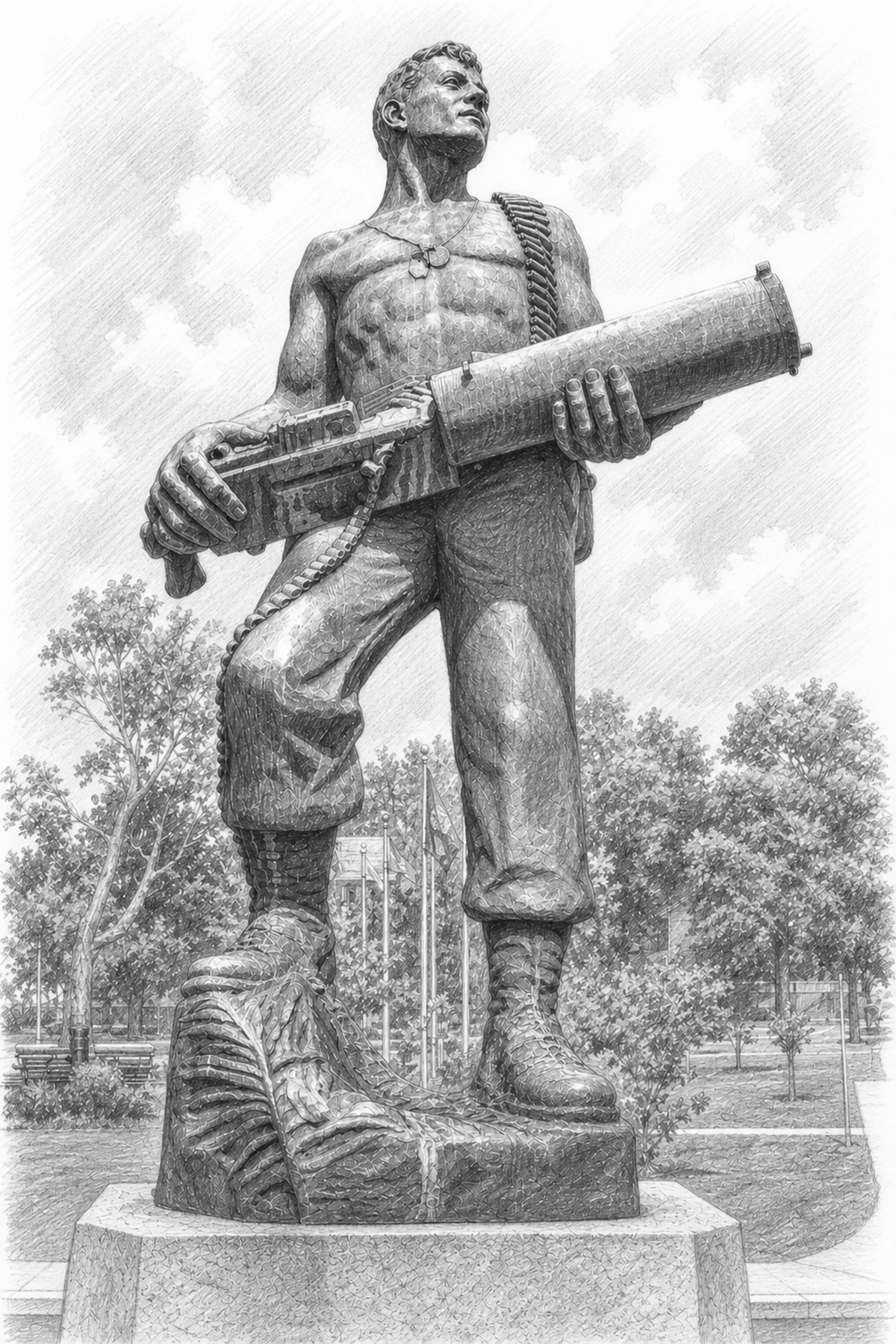
Gunnery Sergeant John Basilone, USMC. Born 4 November 1916 in Buffalo, New York. Killed in action 19 February 1945—D-Day at Iwo Jima.
He is the only enlisted Marine of the Second World War to receive both the Medal of Honor and the Navy Cross.
Guadalcanal, October 1942. Sergeant Basilone, 1st Battalion, 7th Marines, 1st Marine Division. His section of heavy machine guns held a ridge against a regiment-strength assault. When his guns were overrun and his ammunition ran low, he fought on—working a machine gun and a pistol, killing 38 of the enemy from his emplacement, repairing guns under fire, and running ammunition through hostile ground himself to keep his line firing. A Marine who was there, PFC Nash W. Phillips, put it plainly: Basilone "had a machine gun on the go for three days and nights without sleep, rest or food." The line held. President Franklin D. Roosevelt signed his Medal of Honor citation.
He came home a national hero. The Marine Corps sent him on a war bond tour and offered him a commission and a stateside post for the duration. He turned it down. He asked to go back to the fleet, and he kept asking until they let him.
Iwo Jima, 19 February 1945. Gunnery Sergeant Basilone, 1st Battalion, 27th Marines, 5th Marine Division, went in with the first wave onto Red Beach. Pinned down under heavy fire, he single-handedly destroyed a Japanese blockhouse while braving smashing bombardment of enemy heavy-caliber fire, then guided a tank through a minefield under fire. He was killed that same morning, still moving his Marines forward. The Navy Cross was awarded posthumously.
He rests at Arlington National Cemetery. The Navy named a destroyer, USS Basilone, in his honor in 1949.
He could have finished the war safe, famous, and commissioned. He went back to his Marines instead.
Service record and decorations per the U.S. Marine Corps History Division. Semper Fidelis.